About the Project
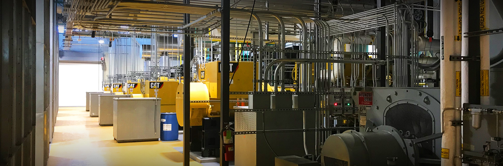
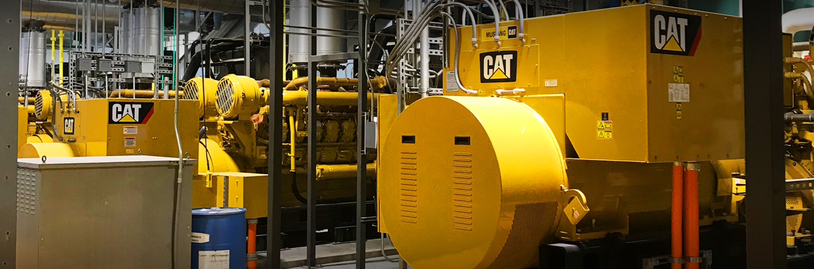
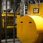
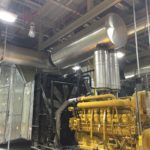
The VAMC CHP project is located on the VA facility in the medical center. Our work included HVAC, plumbing and controls. It had many facets including a new building from the ground up and integrating it with existing buildings and systems already in place. The new building houses 4 diesel generators, 1 natural gas generator and 1 bio diesel generator which are used to power the entire VA campus when needed. Thru 3D BIM coordination drawings we were able to complete this project with minimal conflicts.
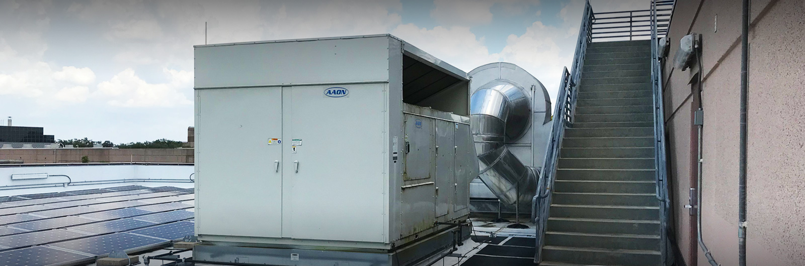
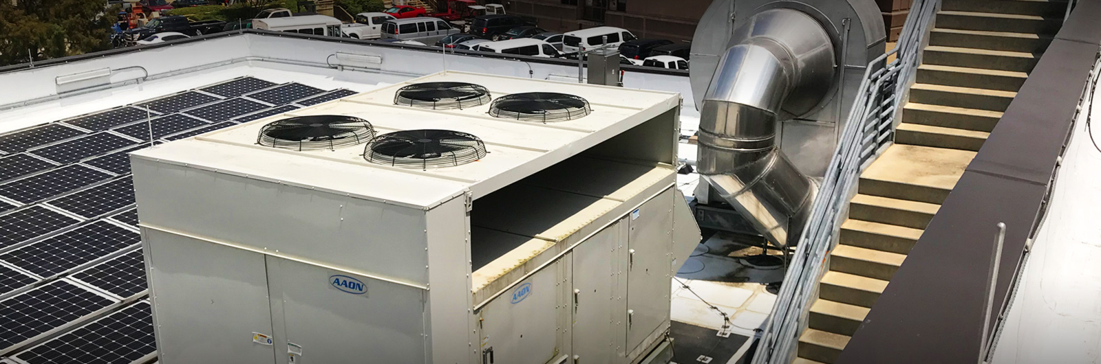
 This project included installing a new chiller, chilled water pump, RTU, 2 Cain heat exchangers, 3 VAV’s, 6 wall mounted exhaust fans, 49 roof mounted gravity hoods to include sound attenuators, six 144” x 240” x 120” wall mounted ventilation exhaust sound attenuators, six 72” x 72” x 244” engine exhaust sound attenuators, 2 glycol water pumps, 4 plate and frame heat exchangers and 7 VFD’s.
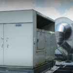
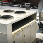
On the HVAC side it began with removing an existing chiller and replacing it with a new 1000 Ton chiller. It included tying into existing 20” condensing water lines and running 14” condensing water lines to the new chiller. It also included installing a new chilled water pump and associated 12” chilled water piping. We then had to integrate it into the existing building management system.
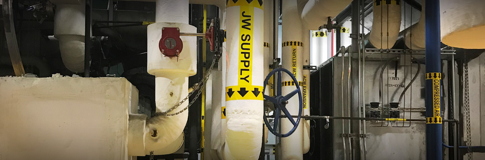
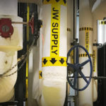
As this was going on, we worked on underground piping for the new building. This consisted of 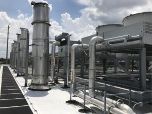 running 6” welded pre-insulated glycol hot water supply and return piping. The pipe came through the floor of the new building, ran underground and continued up the exterior wall of existing Building 103 and onto its roof. It continued over the roof of Building 104 and into the tunnel system. In the tunnel system it crossed under the road and tied into two new heat exchangers that integrated with the VA’s existing domestic hot water and the heating hot water for the hospital in the main mechanical room of Building 100. This piping included many expansion joints and mechanical slides for expansion and contraction. The purpose of this piping is to use the heat generated from the generators to help heat the domestic hot water and heating hot water systems in the existing buildings.
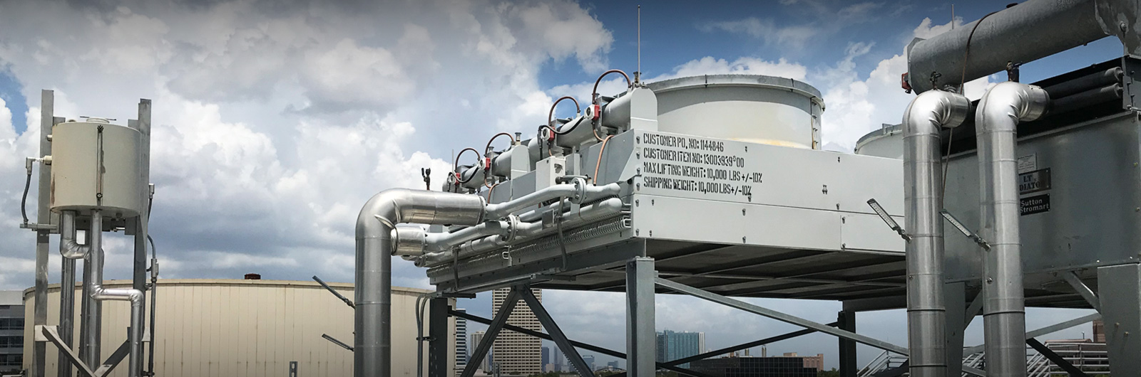
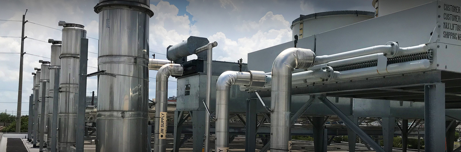
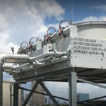
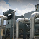
When the building was going up we continued with the glycol water lines and started to install the exhaust piping for the generators. On the 4 diesel units this consisted of running 26” double wall exhaust piping. This piping started with an expansion joint at the generator, thru a muffler and then up thru a thimble in the roof and terminated with a flip top cap. This piping required many supports welded to the structure. Generator 5 had 26” and generator 6 required 32” exhaust piping running thru SCR Catalysts, then thru the Cain heat exchangers and then thru the mufflers. Generator 6 also required running thru the tilt wall thru an exhaust fan, back into the building, thru another muffler and then thru the roof.
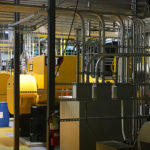
After the generators were installed, we installed all the sound attenuators and roof hoods, and began to complete all the interconnect piping for the generators. This included after cooler water, jacket water, compressed air piping, control wiring to include panels, and urea piping to the SCR dosing panels. When the lower roof was complete we installed the RTU and all associated ductwork. In the switchgear room we installed all the VAVs, VFD’s and controls. When the high roof was complete we installed all the roof top piping to and from the radiators and generators.
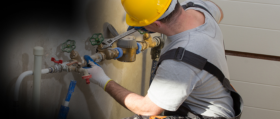
On the plumbing side we installed a high pressure natural gas system, sanitary waste and vent piping, water piping, the urea system, compressed air system and a 1000 gallon oil separator. The underground gas piping was completed using plastic fusion piping and dielectric risers. This piping was installed with a tracer wire and buried gas pipe tape as we backfilled. The above ground piping was run with butt weld and screwed fittings as required.
Sanitary waste and vent piping below grade was run out of PVC and all above ground pipping was with no hub cast iron pipe and heavy duty no hub bands. It was run to floor drains for each generator, 1 toilet, 1 lavatory and 1 drinking fountain in the control room. It also picked up an emergency shower and eyewash in the generator bay and a mop sink and floor drains in the air compressor mechanical room.
 The water system was completed with all copper piping and sweat fittings. All water piping was insulated and heat traced to prevent freezing. The hot water piping included 2 instantaneous gas fired water heaters vented with double wall pipe thru the roof.
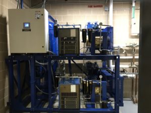
The urea system was completed using schedule 80 PVC piping. This piping and the 2500 gallon tank were also heat traced and insulated. The system consisted of the storage tank, 2 pumps one each for generators 5 sand 6, a fill station on the outside wall and 2 control panels integrated into the BMS. This system is operated by a call to run signal from the BMS. When a generator kicks on it starts the urea pump for that generator. The unused urea is returned to the storage tank thru a return line.
The compressed air system consists of Schedule 40 black steel pipe with screwed fittings. This piping was run to generator six and was used to help start the generator.
When work was completed we ran thru all systems and conducted videotaped owner training sessions for educational purposes on all functions of the new systems. After that we ran thru an extensive 260 hour continuous run test making sure all components worked as required and specified.